

| EDWARD EVERS | Robot Workshop | PC Controlled R/C Car |
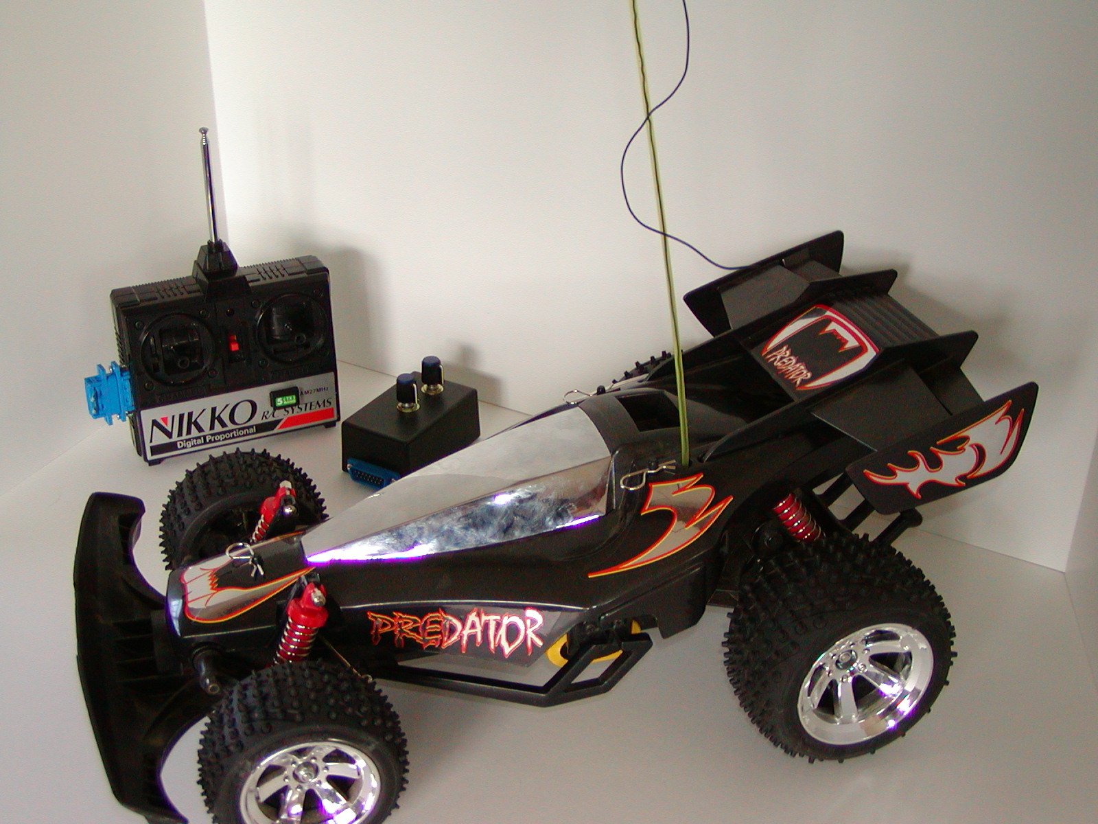
This project involved taking an ordinary r/c car, the Nikko Predator, and wiring its remote control to a computer. The computer is the brain, communicating with its body the car via radio waves.
This is excellent because the vehicle is readily available at most toy and hobby shops, the design is modular and easy to work with, and takes full advantage of the processing power of a modern computer (which people building this project may already have) without the vehicle having to lug all that weight around (and without the risk of it lugging the computer off a cliff, or into a pool).
One of the first requirements of the project, was to make all the modifications to the car and its transmitter without messing up the basic function. So you can still drive the car around the way you normally would.
A joystick connected to the computer can be used to take the place of the two sticks on the usual r/c remote. (The computer keyboard can also be used.) The buttons on the joystick trim the controls, and the joystick's trigger starts and stops the recording mode, so you can record manuevers and play them back.
The brain can tell the body to do 2 things:
Here's what the body can sense:
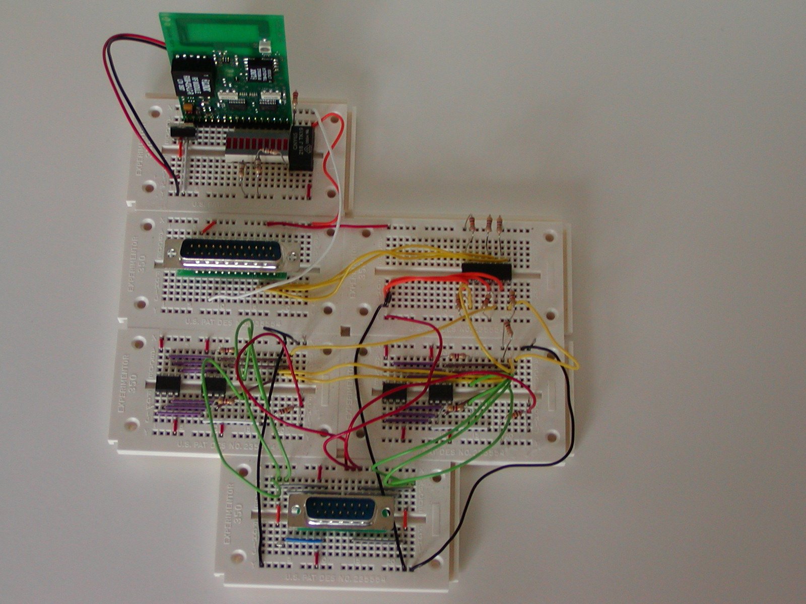
The device connects to a PC by plugging into the parallel port. It connects to the remote control unit by a breadboard I put together. [photo] All the programming is done in C++. I built a class that models the potentiometers in the car's remote.
Sensory information is communicated via a Parallax transmitter (200' range) on the car, and a Parallax receiver on the board plugged into the computer. [links] The sensory information goes into a BASIC Stamp board which tells the software in the computer what's going on. The computer makes all decisions. "All decisions" currently consists of simply backing up at full speed when something is closer than about 24". The software does not scale the car's behavior based on the car's speed, but it will when the speed sensor is put into the car. The sensors (Dantech SRF04) have a very narrow beam that reaches out about 6 or 9 feet. [link]
There will be a video of the procedures available soon.
There was some trouble at first with parallel ports on different computers acting differently, but that's all straightened out now.
It would take a couple of hours to build this from scratch. Breadboard interfaces are very useful.
Remote Control Car Project

        3 optocouplers
        4 10k digital potentiometers

        Parallel Port
            Pin  1 Data 0 - Digital Potentiometer A (Steering) increment toggle
            Pin  2 Data 1 - Digital Potentiometer B (Driving) increment toggle
            Pin  3 Data 2 - Shared Digital Potentiometer Up/Down select
            Pin 11 +Busy  - Ultrasonic detect
            Pin 24 GND

        Custom Port (DB15)
            Pin Layout: (female)
            (15)    (13)    (11)    ( 9)    ( 7)    ( 5)    ( 3)    ( 1)
                (14)    (12)    (10)    ( 8)    ( 6)    ( 4)    ( 2)

            Pin Layout: (male)
            ( 1)    ( 3)    ( 5)    ( 7)   (  9)    (11)    (13)    (15)
                ( 2)    ( 4)    ( 6)    ( 8)    (10)    (12)    (14)

            Connections:
                Pin  1 - +9V (RC Transmitter)
                Pin  2 - Ground (RC Transmitter)
                Pin  3 - Board connect Drive Pot Top
                Pin  4 - Board connect Drive Pot Bottom
                Pin  5 - Drive Pot Top
                Pin  6 - Drive Pot Bottom
                Pin  7 - Drive Pot Wiper (line tap)
                Pin  8 - [NC]
                Pin  9 - Steering Pot Wiper (line tap)
                Pin 10 - Steering Pot Bottom
                Pin 11 - Steering Pot Top
                Pin 12 - Board connect Steering Pot Bottom
                Pin 13 - Board connect Steering Pot Top
                Pin 14 - [NC]
                Pin 15 - [NC]
Install encoder disk so the car can tell the computer how fast it's going.
Update transmission from car to send actual distance information to the computer.
The car will have additional sensors.
The program will actually be able to map the territory the vehicle is running around in.
The car can be programmed to achieve goals, such as finding certain objects, reacting to light or movement, deciding on the best route from one location to another.
The electronics will be put onto an etched circuit board.
| EDWARD EVERS | Robot Workshop | PC Controlled R/C Car |
Modified 2003-02-18
Copyright © 2003 Edward Evers